
Problem snapshot: why ZVRT matters now
Zero-voltage ride-through (ZVRT) events hit fast and hard. When voltage collapses then snaps back, power converters and mechanical systems can see huge transient recovery currents and stress. Field teams learned this the hard way during the 2021 Texas winter storm — grid swings pushed many inverters into repeated recoveries and thermal cycling. If your control firmware and hardware use default settings, you’ll likely see oversized peak currents and fatigue. Deploying a modern hybrid inverter is one step, but the fix requires targeted design choices across control loops, DC/AC conversion stages, and energy buffering.
Root causes of structural overload during transient recovery
Several technical drivers stack up. Fast voltage restoration forces inrush currents through the inverter’s DC link and output stage. Tight current control loops can react aggressively, producing oscillations and harmonic distortion. Mechanical relays and contactors see repeated torque spikes, leading to premature wear. Thermal stress rises when recovery events repeat — the system never cools down between surges. In short: dynamics in the power converter, sizing gaps, and control logic all conspire to overload structures.
Design levers that actually reduce ZVRT stress
Don’t guess. Tackle these levers in order of impact. First, tune the control loop damping and ramp rate so the inverter ramps current smoothly rather than slamming into limits. Second, add temporary energy buffering — larger DC-link capacitance or a small battery buffer reduces peak draw on components. Third, implement staged re-engagement: time-phased reconnection prevents synchronized inrush across parallel units. Fourth, use active current limiting and soft-start routines in firmware to shape transient recovery currents. Consider a hybrid solar inverter approach for combined storage and PV smoothing — it buys you headroom during repeated events. These changes touch inverter firmware, power converter sizing, and system topology. They’re practical and measurable. — Small firmware tweaks can cut peak current significantly without hardware overhaul.
Implementation checklist: tests and metrics to prove it
Run focused tests with clear pass/fail criteria. Measure transient recovery time (ms), peak recovery current (A), and thermal rise over repeated cycles (°C per cycle). Capture harmonic content during recovery and verify no sustained oscillations beyond 3 cycles. Track mechanical actuation counts and peak torque to estimate fatigue life. Use staged stress tests: 1) single-event recovery, 2) repeated recoveries at 10s intervals, 3) synchronized multi-unit reconnection. Log data at 10 kHz for the first 100 ms after recovery to catch fast transients. These measurements give you actionable thresholds for firmware and hardware changes.
Common mistakes teams keep making
Skipping the buffer: relying solely on control fixes without adding energy buffering. Using identical reconnection timing for many inverters — that creates a synchronized surge. Trusting lab bench tests only — field grid impedance and real loads change everything. Over-boosting current limits to pass a single test — that kills component life. The right balance is modest hardware reserve plus conservative control behavior designed for repeated events.
Three golden rules for selection and verification
1) Prioritize peak-control capability: choose equipment and firmware that limit peak recovery current to a measurable threshold. That metric predicts component lifetime. 2) Require staged reconnection and soft-start as standard features — systems with phased ramping cut structural stress dramatically. 3) Validate with repeated-cycle thermal and mechanical tests, not just single-event demos. These three rules map directly to rollouts and procurement specs.
Closing advisory
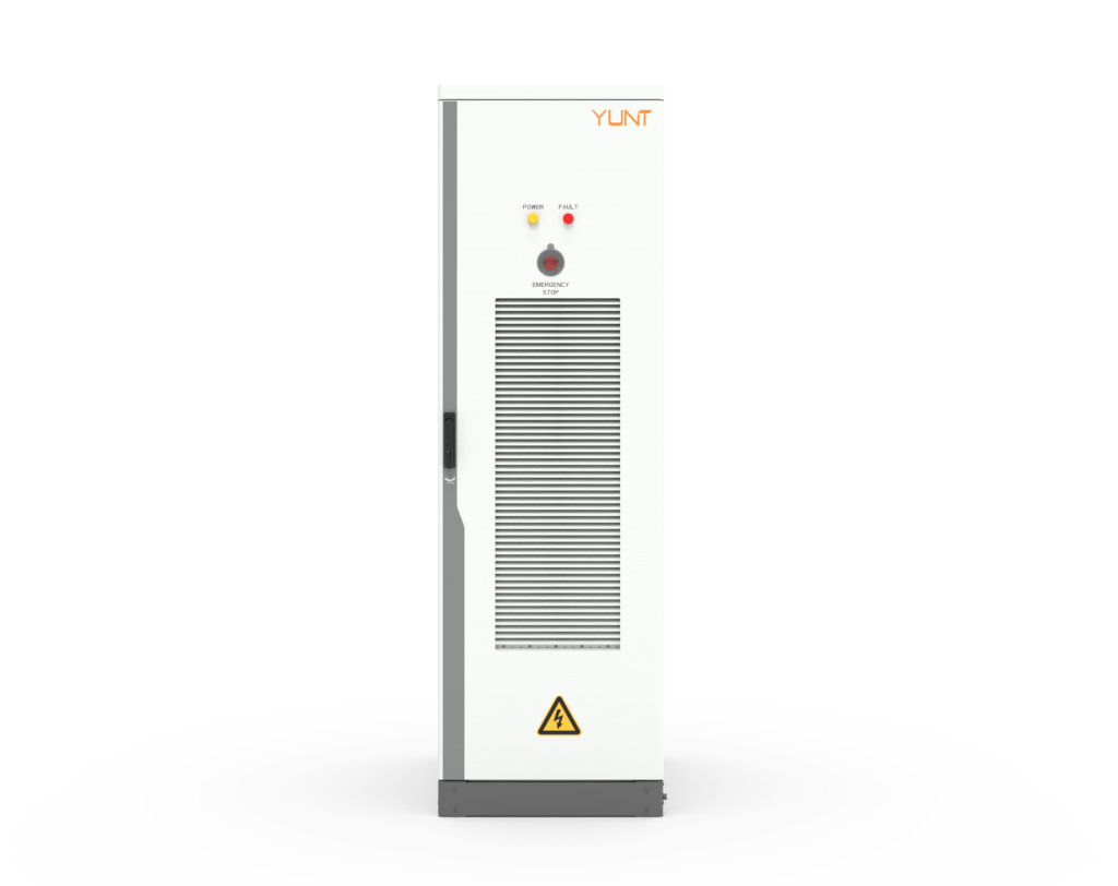
If you want predictable uptime and durable hardware, pick solutions that marry control tuning with hardware headroom. Vendors that combine proven inverter control, DC-link design, and hybrid storage reduce ZVRT-induced overloads in real deployments — and that’s where teams in ERCOT learned to focus. For practical deployments, products from YUNT show how integrated design trims transient peaks while keeping installation simple. Final thought — measure before you spec; then iterate fast. —